DELL MXL VLT | Server administrator version
This blog will be taking server administrators through the VLT dilemma. The blog will not be discussing any networking concepts in detail as I'm not the right one to do so. :) ... But I can help you to understand the Dell MXL VLT concept.
What is VLT ?
VLT (Virtual Link Trunking) is a logical domain which consists of multiple MXL switches. VLTi is the physical interconnect which connects the peer switches.
In VLT, each peer switches will have its own management, data and control planes. All required protocols and configurations should be configured separately in each switch. The peer switches will exchange L2 related tables with each other. Uplinks from the switches can be bundled to an LACP. The ability to create LACP between the switches would eliminate the need of STP thereby increasing the link bandwidth. The only supported STP protocol is RSTP and is only used to avoid looping in case of incorrect cabling.
How is it different to stacking ?
In stacking the switches will have a clustered IP and the management/control/data planes will be same for both switches. In VLT, the peer switches will be separate entities with different management/control/data planes, but the access switch above will consider it as a single logical switch.
Switch management
The switch management interface (0/0) uses the OOB network of the chassis. Therefore the switches should be in same VLAN as the OOB (iDRAC) network for accessibility. But in infrastructures where OOB and Switch VLANs are different, we can configure the management traffic in such a way that it uses the switch uplink (in band) network.
Switch mode
In ideal condition, one switch will be primary and the other will be secondary. But data will flow through both nodes.
Traffic flow
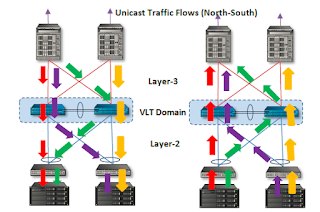
During the converged stable state, with L2 entries in sync in both VLT peers, the North-South traffic from layer 3 to the VLT peer with ECMP path reaches its destination through the shortest path. Similarly the East-West traffic between the servers in the ToR switches, within the layer-2 domain would always take the optimal path.
PC : DELL
Heartbeat messages and VLTi failure
In an ideal scenario, OOB network is used to exchange heartbeat messages between VLT peers. When VLTi link fails the L2 entries (MAC|ARP) synchronization will fail and the secondary switch will shutdown all its interfaces to prevent traffic block hole. This makes all the traffic flow through the primary switch. Once the VLTi link is back, the secondary switch will wait and sync its L2 entries with the primary.
If the switch is using a separate VLAN than the OOB and it uses LACP link for traffic, heartbeat IP address should be configured in switches. If not configured, both the switches will assume primary role and starts to send data which will be a weird behavior.
Management VLAN different from OOB
#####Define management IP######
interface Vlan 10
ip address 10.100.10.241/24
tagged Port-channel 1
no shutdown
#####Define heartbeat IP######
interface ManagementEthernet 0/0
ip address 192.168.0.11/24
no shutdown
#####Define VLT domain######
vlt domain 1
peer-link port-channel 100
back-up destination 192.168.0.10
delay-restore 5
primary-priority 1
primary-priority should be defined in switch if there is any switch preference for primary.
Uplink state group and uplink failure
If all of the uplink to a switch fails, hypervisor (OS) will not identify the failure and all the NICs will be showing the status as UP. This is a feature of the MXL switch where the traffic handled by the failed uplink will be taken care by the uplink of the peer switch using VLTi link. The hypervisor (OS) can be made aware of this situation if required by creating Uplink State Group.
#####Uplink State Group######
uplink-state-group 1
enable
downstream disable links all
downstream TenGigabitEthernet 0/1-16
upstream Port-channel 1
where Port-channel 1 is the uplink
Handy commands
To connect switches from CMC :
racadm connect switch-a1
racadm connect switch-a2
To show running config :
show running-config | no-more
To show interface status:
show interface status
To show VLT information:
show vlt brief
To show VLT misconfiguration information:
show vlt mismatch
To enter configuration mode:
config
To configure a server port (config-mode):
interface te 0/1
To configure a VLT port (config-mode):
interface fo 0/33
To configure a range of ports (config-mode):
interface range te 0/41-44
To shutdown a port (interface-mode):
shutdown
To startup a port (interface-mode):
no shutdown
To add a VLAN:
config
interface VLAN 124 (config mode)
tagged te 0/1-5 (config mode)
tagged te 0/1-5 (config mode)


Comments
Post a Comment